Overview:
LEDs can uniquely control the amount of three primary colors (red, green, and
blue) to create a desired color. Thanks to this feature, they are now an
attractive and practical component in Electronics and Lighting industry. An RGB
LED has one common pin as well as three pins for red, green, and blue colors. We
can combine these primary colors to create countless colors by controlling these
pins with a PWM pulse signal. (The number of colors depends on the resolution of
the generated PWM signal).
These components are controlled by microcontrollers and PWM drivers. But, since
each microcontroller has a limited number of pins and output current, various
modules have been developed to increase PWM channels for controlling RGB LEDs.
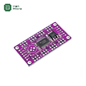
TLC5947, which has 24 PWM output channels, is a widely used module. In this
tutorial, we’ll introduce and set up this module.
The TLC5947 module is a constant-current LED driver module with 24 output
channels. On this module, we can separately control 24 rows of LEDs (or 8 rows
of RGB LEDs) with a PWM signal.
The resolution of the PWM signal is 12 bits, meaning 4096 PWM steps are used to
handle each output channel.
We communicate with the module through the SPI signal which has a voltage level
of 3-5 volts.
Several modules can be connected, all of which are controlled by three data
lines. In this way, we can easily have a large number of controllable PWM
outputs with only 3 microcontroller pins.
Unlike most electrical components that operate with a constant voltage, LEDs
work with a constant current. In this module, the output current of each pin is
fixed at 15mA. Of course, in the IC of this module, the current sinks; meaning
it flows from the common anode pin to the control pins rather than the other way
around.
The output channels of the module are common anode types. These common pins are
connected directly to the module input voltage pin.
Notice : An LED’s positive pin is called an "anode." A module is said to be a
common anode if all of its positive output pins are connected to one another,
and each output is controlled by the cathode pin. To connect the LEDs, make sure
to connect the positive pins to the common anode and the negative pins to the
channel output. When preparing RGB LEDs, keep in mind that they must be common
anode types.
The input voltage of this module ranges from 5 to 30V. And in order to
communicate, the voltage of the data pins should be between 3 to 5V.
Warning : This module is not suitable set up DC motors.
Specifications:
Input voltage: 5 to 30 volts
24 channels; a constant current of 30 mA
12-Bit (4096 Steps) PWM
CMOS Logic Level I/O
Data transfer frequency: 30 MHz (board used alone)
Data transfer frequency: 15 MHz (cascaded devices)
4MHz internal oscillator
Operating temperature: -40 to 85 °C
ماژول کنترل PWM - درایور ال ای دی 12 بیتی TLC5947
- تولید کننده: China - A
- دسته بندی ها:
- - سنسور و ماژول رنگ ، نور ، لیزر ، مادون قرمز IR ، اپتوکانتر و UV
- کد محصول: RG_110_16E013_000000_14300
- موجودی: 8
-
قیمت پایه : 10,929,600ریال
ارسال رایگان سفارشات بالای 5 میلیون تومان
تعداد بازدید: 2082
پرسش و پاسخ مشتریان
برچسب ها: ماژول کنترل PWM - درایور ال ای دی 12 بیتی TLC5947, RG_110_000000_000000_14300, سنسور و ماژول رنگ ، نور ، لیزر ، مادون قرمز IR ، اپتوکانتر و UV
